February 18, 2024
Casio QV-10 Makeshift Data Cable
This post is about a makeshift way to get images off the vintage Casio Qv-10, Casio QV-11, etc digital cameras from the 1990s. Fortunately had all the supplies needed in my desk drawers and etc. Suspect there's very few others that will, but fortunately they're all easily available to purchase and are inexpensive.
Couldn't find my Casio QV-10B anywhere around my usual storage spots, so as a result was missing the Casio SB155 serial cable. A similar camera, the QV-11, was easy to find on ebay in 2024. The data cable, however, was not packed with most of the listings and did not seem easy to find on web searches either. There were some results for building one, but while looking into that it seems there were enough suitable parts laying around here to use instead.
Here's the QV-11 that I got taking its own selfie in a mirror with a camera shutter command driven by the makeshift serial cable. Following this image will be the rest of the article on how you can recreate the data transfer setup.
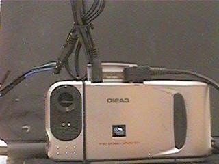
Here I would normally I write: Click image to view higher resolution. These cameras are old, so that's the actual resolution. Clicking it will open to just the image anyway, templates and such.
More info about how to create this setup for transfer or info to make your own flavor after the click below.
The information, links, and various thoughts info follows below. Disclaimer: If you follow these instructions then you are on your own. I take no responsibility for your actions and am not trained as an EE. If you break your camera, laptop, computer, peripherals, cables, your home, and/or yourself by following this then it is all on you.
Table of Contents
- The tools and supplies needed
- The Serial Cable
- The Optional Power Cable
- The Software
The tools and supplies needed
The ingredients and tools
- A QV-10, QV-11, or other cameras that use same SB155 cable
- A computer, this description assumes Linux or Chromebook
- Open source QVPlay software (qvplay-0.95.tar.gz)
- A headphone cable or adapter with 2.5mm plug
- A3.3V/5V USB to serial adapter with Prolific chip
- Something to use to connect your 2.5mm cabling and USB serial cable
- Optional: a power plug
The Serial Cable
Disclaimer: The Casio runs at either 5V or 6V, so do not run it with a PC serial cable or a USB to serial adapter running at PC voltages. Also, the USB to serial at 5V and 3.3V seems to tolerate the output given by the QV-10, but they're mismatched and unsure how long the adapter will hold up. Doing a voltage level shifter is not discussed here, maybe for a later article if curiosity gets to me.
There's several schematics and information online about building a SB155 style serial cable, but I mainly used for learning as I lacked the parts on hand that are shown in their schematic. Here's a few that I found in case you want to abandon this and do a closer match to the original: SB155 with two different schematics and four different ways to build one.
For my build, generally need a low voltage USB to Serial adapter to connect to the computer's USB at one end and to the QV-10 at the other end via a 2.5mm headphone plug.
For the USB to Serial, I had a NooElec USB to Serial adapter on-hand that looks like this one here.. On Linux or Chromebook no driver was needed.
To interface to the camera, you could solder the the jumper cables from the USB to Serial adapter directly into some 2.5mm headphone plug and cable. However,I didn't want to irreversibly modify any of my cables or adapters. On hand had a headphone adapter cable with the 2.5mm plug on one side and a socket for a 3.5mm headphone plug on the other. How to connect this together with the USB Serial? Well, happened to have a 3.5mm male to male AUX cable on hand to plug into the 2.5mm to 3.5mm adapter. Also had a dead phone in my "electronics stuff" box which I could harvest a 3.5mm headphone jack. While there, of course, have Dupont or jumper cables.
The connection all up is: USB to Serial connects to jumper cables (Dupont) on Tx/Rx/Ground pins of the adapter, extra jumper cables with the opposite mating get soldered to Right/Left/Ground(Sleeve) of the harvested 3.5mm headphone jack, the 3.5mm AUX extension cable plugs into the headphone jack and into the 2.5mm to 3.5mm adapter, and finally the 2.5mm plug goes into the camera. The headphone tip is Transmit (Tx), the ring is Receive (Rx), and the shield is ground. When you get to software if the connection isn't working then just swap the Tx and Rx jumper connections, that's the good part of using these instead of soldering.
Here are the diagrams for the above.
The ports on the QV-10, QV-11, etc.
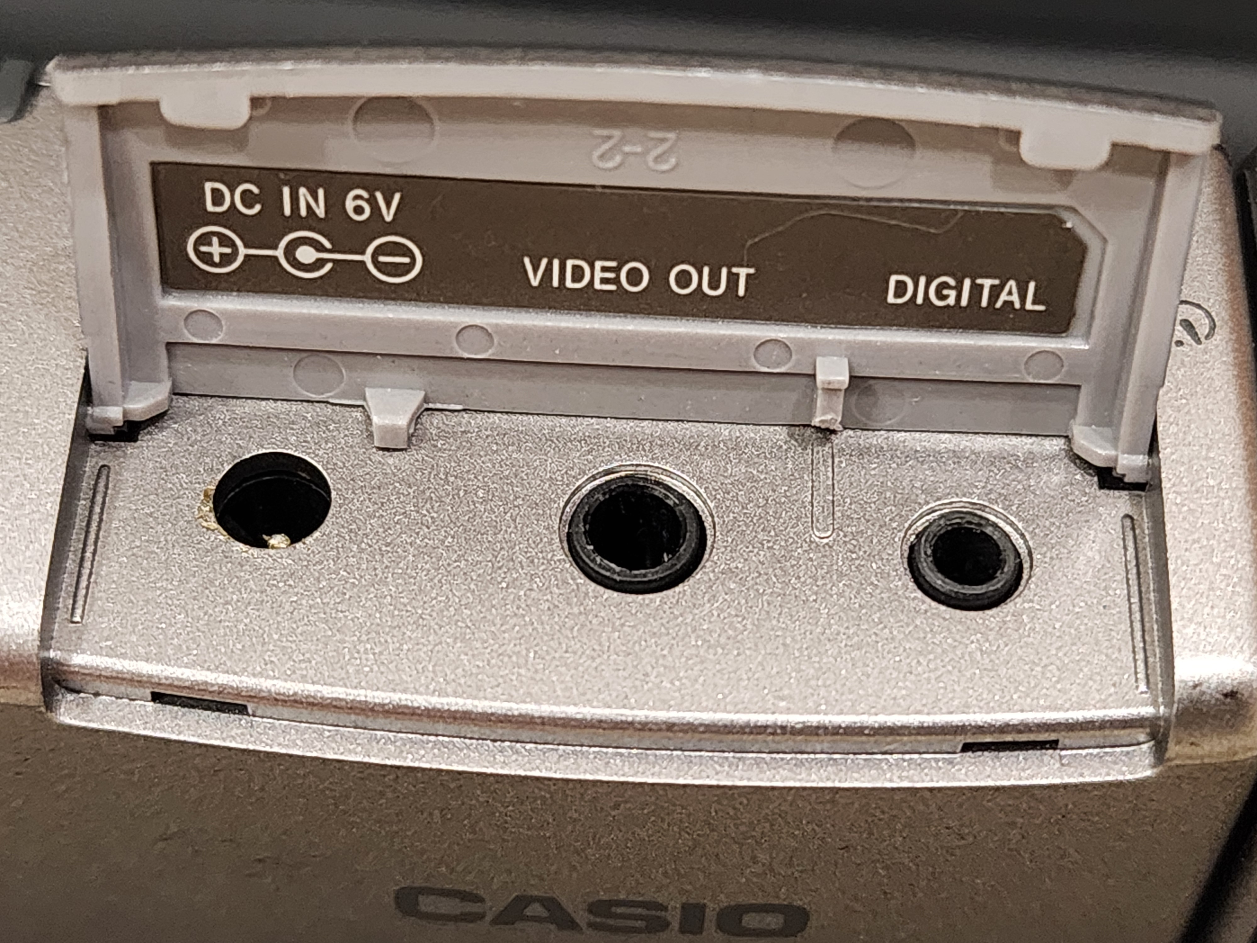
Click image for larger resolution.
The power and data ports plugged in
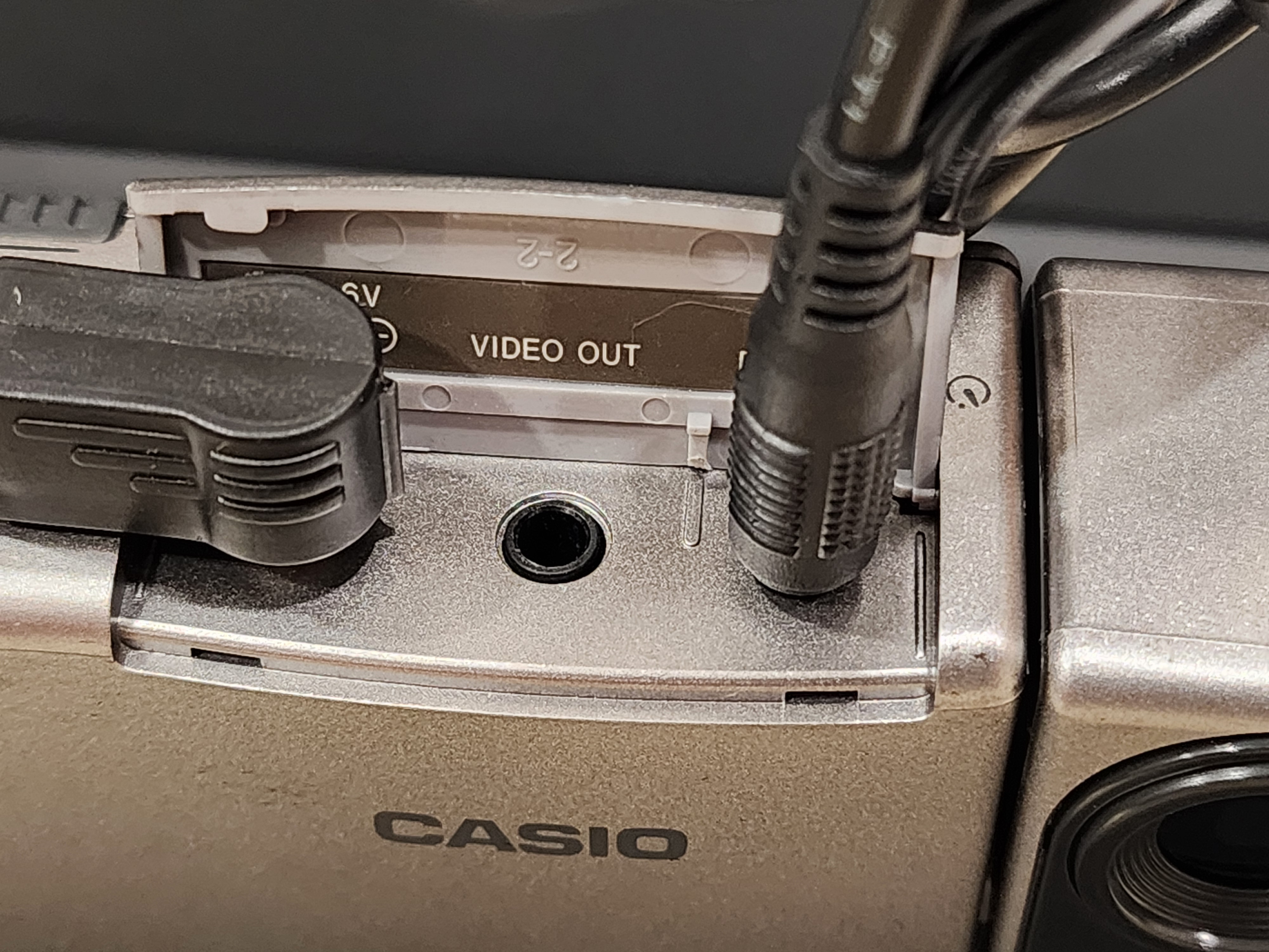
Click image for larger resolution.
The USB to serial adapter connected with the jumpers
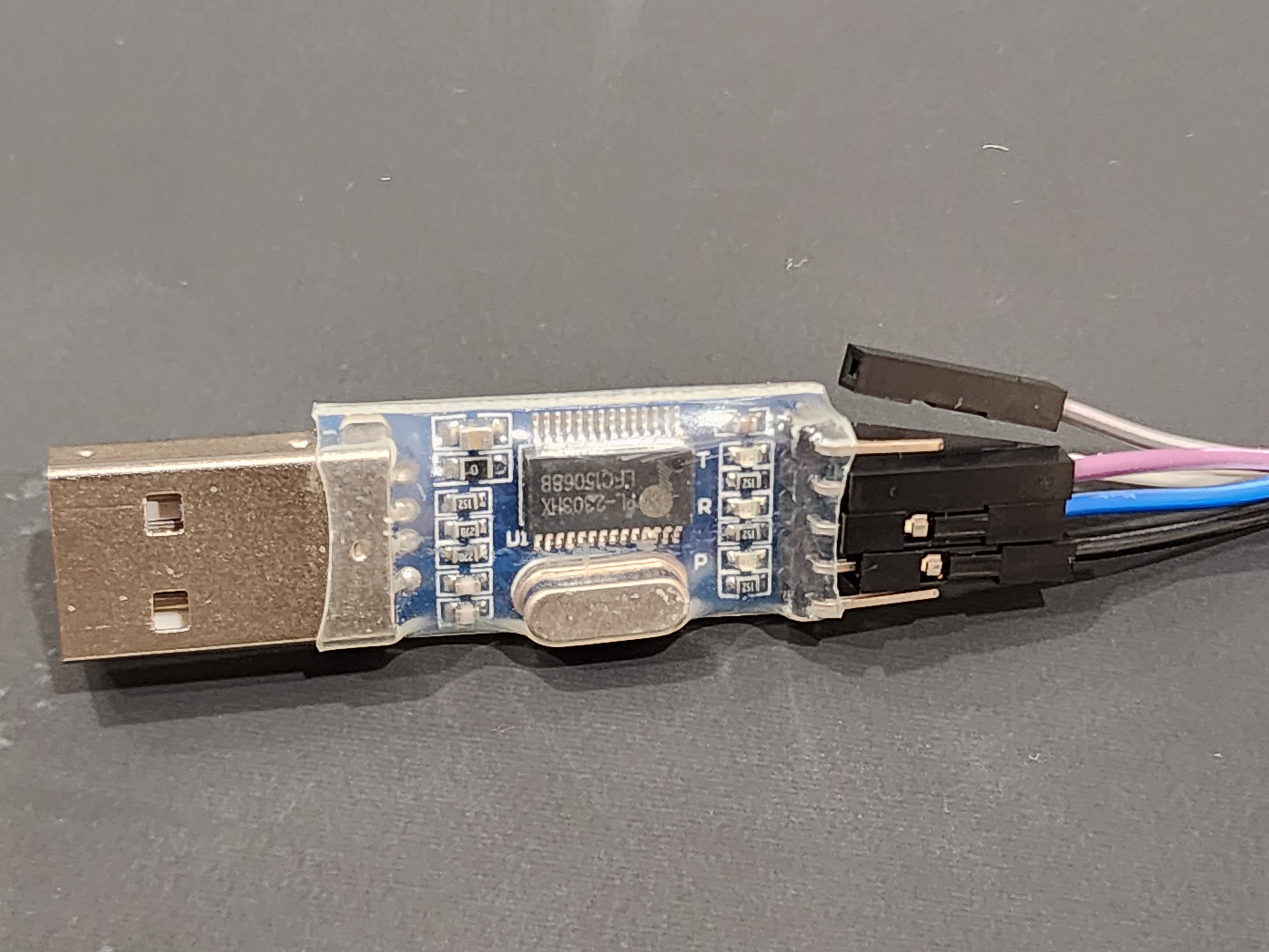
Click image for larger resolution.
The rest of the connections, jumpers and headphone jack
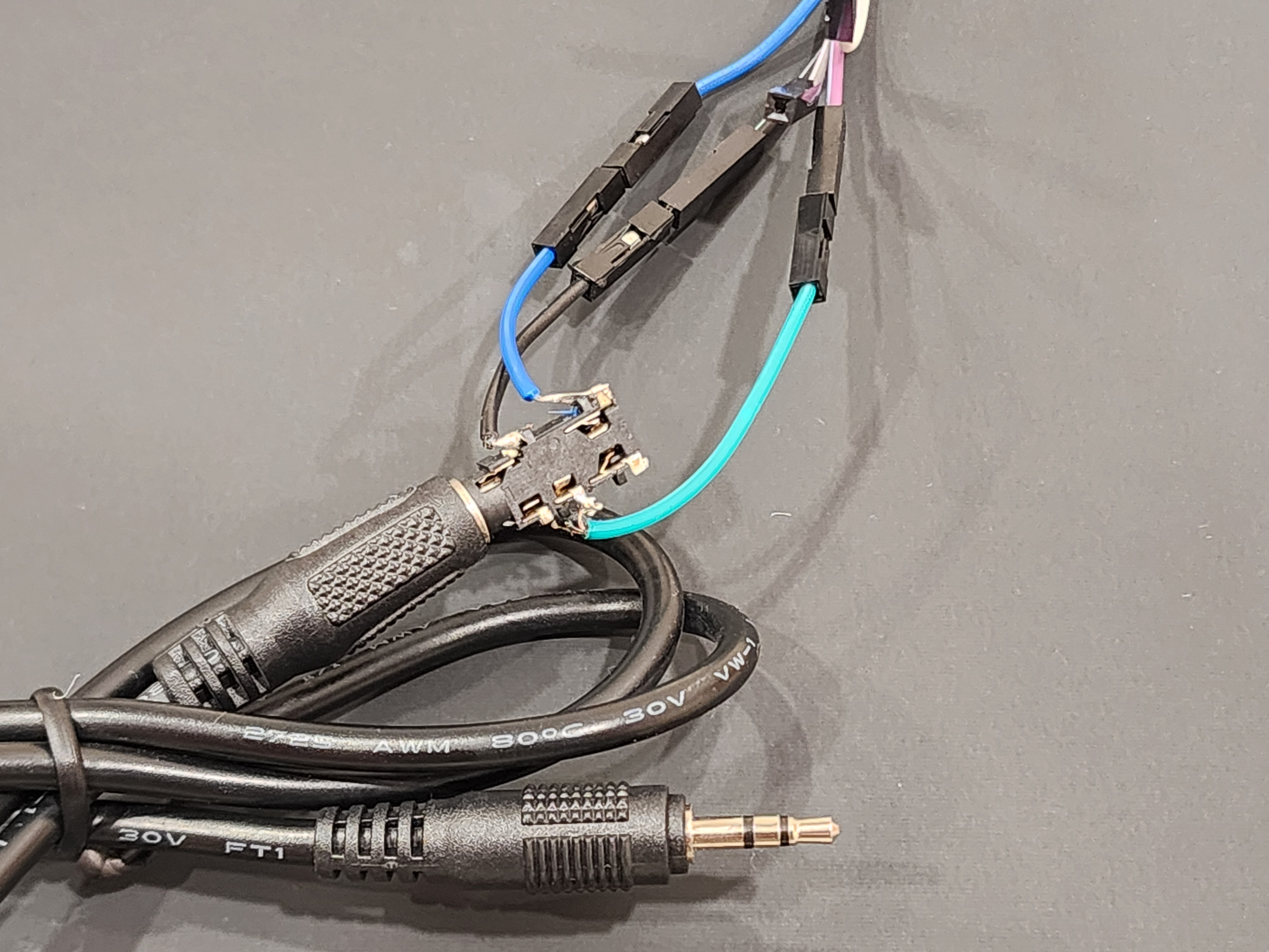
Click image for larger resolution.
The Optional Power Cable
The camera is battery powered, so this step isn't necessary. Thought it was interesting that the Gameboy DMG power supply works for this camera. It is a 6V Tip negative supply of the same dimension. I had a handy USB to Gameboy DMG cable that I had built. The USB supplied 5V, but everything seemed to work fine.
The plus that fits the power connector on the camera is like this one. IF making a USB cable out of it pay attention to tip negative and test with multimeter.
Here's the business ends of the cable plugged into a USB power bank
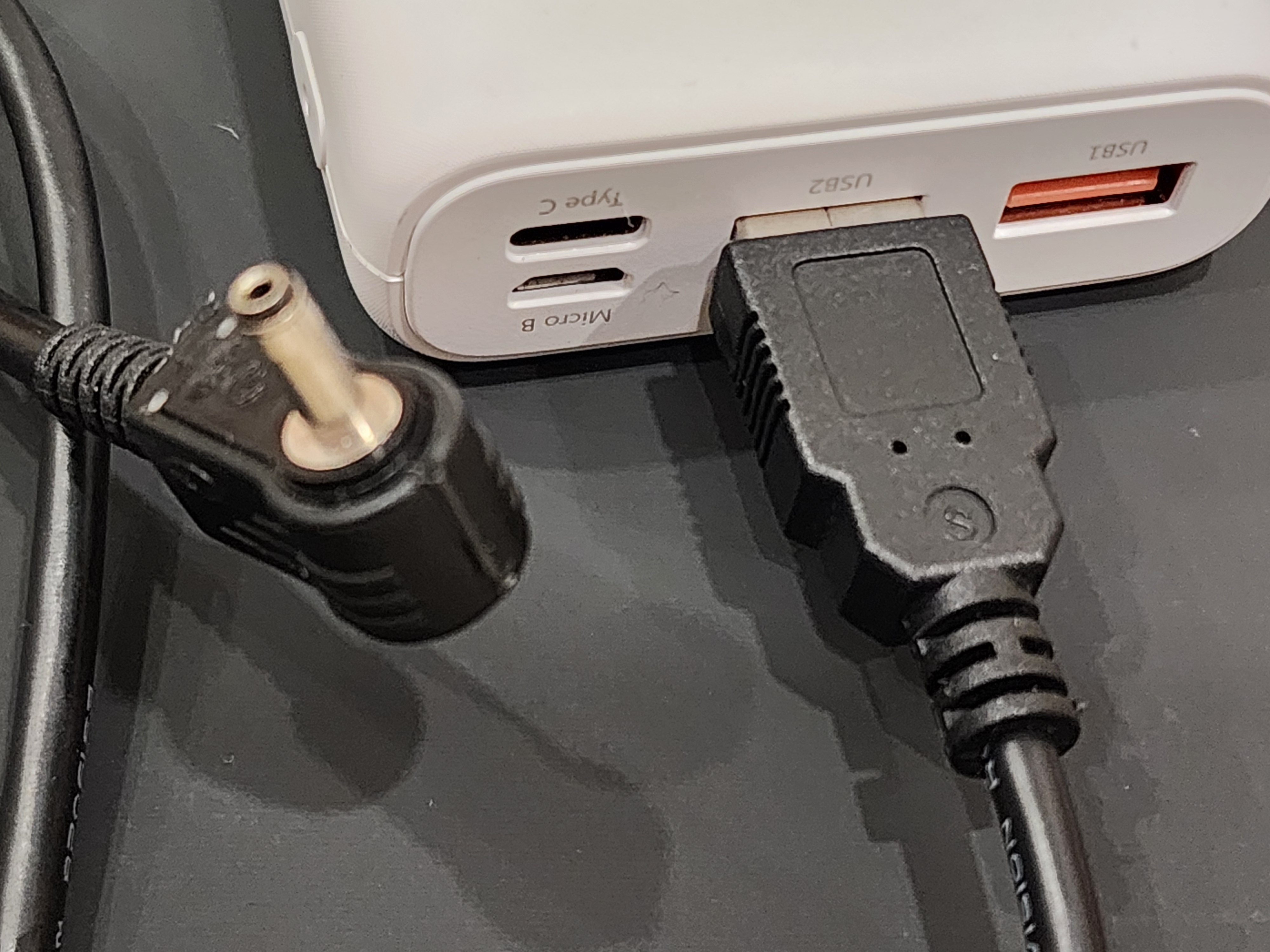
Click image for larger resolution.
The Software
This article discusses the open source software called QVPlay. To download, you can do a web search for "qvplay-0.95.tar.gz" the source code for the program that commands the camera from your computer. I found it here. Casio's original QV-link software would also likely work, but am unsure which Windows versions it is compatible with. If choosing the Windows software then get the instructions on web searching. There's no more info here about that one.
This section consists of:
- Setting up your computer to prep
- Building the QVPlay software
- Connecting the camera and running QVPlay
Setting up your computer to prep
In this article I used a chromebook with a crostini Linux Terminal installed to build and run the software to interface with the Case QV-11. Linux itself works too, tested that too, but unsure if there were any differences in the steps.
1. Go to settings and type Linux and then install the Linux environment.
2. After going through the prompts and installing it, run the Terminal
3. In the terminal type sudo su
4. Now be careful going forward, you're root in your Linux VM sandbox, but on inux you're in a far more privileged area
Installing the build tools to compile QVPlay are putting this in your Linux terminal:
apt-get install build-essential manpages-devRead the prompts, likely answering Y with enter to proceed when needed.
Installing some helper utilities to process the images from the camera
apt-get install libjpeg-progsand then
apt-get install netpbm
Building the QVPlay software
Now you want to download the QVPlay tar as described and or linked earlier. I like to keep these things intact, so make a working directory like qvplay and copy it over.
1. Make the directory
mkdir qvplay2. Go into the directory
cd qvplay3. Copy the QVPlay source code tar to local. Note, you want to use your real path where QVPlay tar is and yes there's a dot at the end.
cp /path/to/qvplay-0.95.tar.gz .4. Enter the directory it extracted to
cd QVplay095/5. The next few parts are mainly from the readme here and also info here. Setup the Linux build.
./setup Linux6. Enter the build directory.
cd obj/Linux/7. Configure the build
./configure8. Go in to your favorite text editor and remove the inline function prefixes from the file called command.c for wbyte, rbyte, and wstr. Then save the file.
9. Make QVPlay
make10. Test it and observe error
./qvplay
Connecting the camera and running QVPlay
Wow, now it is showtime. Make sure the camera has an image on it.
1. Connect the serial cable 2.5mm jack to the camera's data ports as shown in earlier images
2. Connect USB serial adapter into you chromebook
3. In the notification area it will ask if you want to share with Android or Linux and now Choose Linux
4. Optionally plug in the USB power cable or ensure the camera has batteries in it.
5. Turn on the camera
6. Flip the switch on the camera near the LCD to Play
7. Now that the USB Serial is connected and shared with Linux, you need to make a symbolic link to remap the port to the one QVPlay expects. You could avoid doing this by changing it before building QVPlay, but I prefer the manual setup. Also, likely need to do this each time the USB Serial is replugged or computer rebooted. Make sure the serial device name is as what is on your system.
ln -s /dev/ttyUSB0 /dev/qvtty8. Test QVPlay interaction with camera
./qvplay -nYou should see a number like 1 or however many images are on your camera. If not, then try to swap the Tx and Rx connections and do it again.
9. Get an image off of the camera and in the appropriate size. You will want to swap out some of the numbers or filenames, so you get the appropriate image off the camera and do not overwrite a file on your system. Here uses image 3 in the example, but can be any as long as it is equal to or less than what the -n command answered.
./qvplay -S top -g 3 | djpeg | pnmscale -xsize 320 -ysize 240 | cjpeg > 3.jpg
Other info. Sometimes the camera gets non responsive after serial communications, so you can ask QVPlay to reset it.
./qvplay -rYou can recreate the selfie without having to press the shutter button by switching the switch near the LCD to Rec and issuing this command.
./qvplay -tTrackback
You can ping this entry by using http://www.wanderinghuman.com/cgi-bin/mt-tb.cgi/123 .