February 04, 2008
Modifying an EEE PC Preparation
I have an EEE PC on order after I deemed the Ultra Mobile Personal Computer (UMPC) as suitable to me. I would have gone to BestBuy to purchase one, but they have it as online order only. Some people seem to think this is due to the fact that having a non-Windows unit at $300-$400 would hurt margins in sale and re-stocking.
Originally, I was about to purchase an OQO device with the embedded 3G modem for wireless broadband. However, it may be too small in keyboard and it definitely had a high price tag. After some banging around the internet I came across the EEE PC which is in the class of UMPC and has a Solid State Drive (SSD) for storage as well. SSD tend to be more durable for constant lugging around every wheres.
Furthermore, the wizards at the eeeuser website had a forum where people had many innovative hardware modifications to extend the capabilities of the EEE PC. This sealed the deal for me and I promptly ordered one and a RAM module for upgrading. The forum is here.
Click the next link to see how I brushed up on soldering skills to prepare for the arrival of my EEE PC and what I plan to put in the thing.
Since I am relatively new to soldering and especially de-soldering, I went out and got the supplies. In my EEE PC, I intend to do some additional storage, bluetooth, an FM Radio receiver, and possibly an FM Transmitter. Externally, I plan the 3G modem dongle. I don't want to bind that to the EEE PC, since I have many laptops that may need to be lugged to some places and would appreciate the portability of pluggable and un-pluggable 3G Wireless. Additionally, Windows XP is planned for the EEE PC since I am not much of a linux person.
Now I have the supplies, but I don't fancy frigging up my new favorite portable PC or any of the items I intend to embed within it. Staples had a sale of PNY 2G USB 2.0 Flash Memory for $17.99. Since I will be using a USB flash memory in the EEE PC of a larger storage and more expensive kind, it seemed perfect to practice with a throwaway.
I cracked open the case to access the electronics; essentially destroying it. This is fine, since it was bought as a throwaway and had no intent of ever piecing together. All the radio shack supplies were broken open. These included: Flux Solder, Desoldering Braid, really thing solder, handsfree workstation with magnifier, and dual wattage soldering iron. My prior soldering iron would likely run too hot. This particulare soldering iron was selectable at 15 and 30 watts. I used 15W at first, but then moved to 30W when I noticed the solder was not melting well.
There were 6 pins needing attention with a really hot stick. The two outside pins that affix the USB connector were the most difficult to remove. You will notice how frustrated it made me by the damage to the PCB, but the flash drive was still functional after all the operations.
Some lessons learned, which I can apply to some real parts when I get them for the EEE PC.
Basically, the outer two pins that go through the board needed the first attention, so there would be more give to the 4 USB pins in order to melt the solder and bring a thin sharp object underneat after prying upwards. First I melted some flux solder onto the points on each side of the two through-board pins. Then I used the desoldering braid to remove as much solder as I could. I repeated the above a lot more times than I probably needed to, but I Was learning. Eventually there was very little solder on both, so I flipped it upside down and melted the solder on the pin part that goes through the board. While doing that, I gave the PCB board a steady motion of twist and downward pressure. This pretty much was the pressure that would be needed to pop out the part while leaving all the other pins intact (since they were intact by being glued down with solid metal). Eventually it gave and the tip went through the hole on the board.
The same thing was repeated for the other side and the same satisfactory result. Then I flipped it over, remember the USB connector is easier to clamp with one clip inside the connector and the other on the outside. I proceeded to apply a little downward force on the PCB while heating the USB pin on the PC. This disconnected the pin, so I put a thin&sharp&sturdy object underneath to pry it up, so the heat on the next pin doesn't run the risk of re-fastening this one. Repeat that times three.
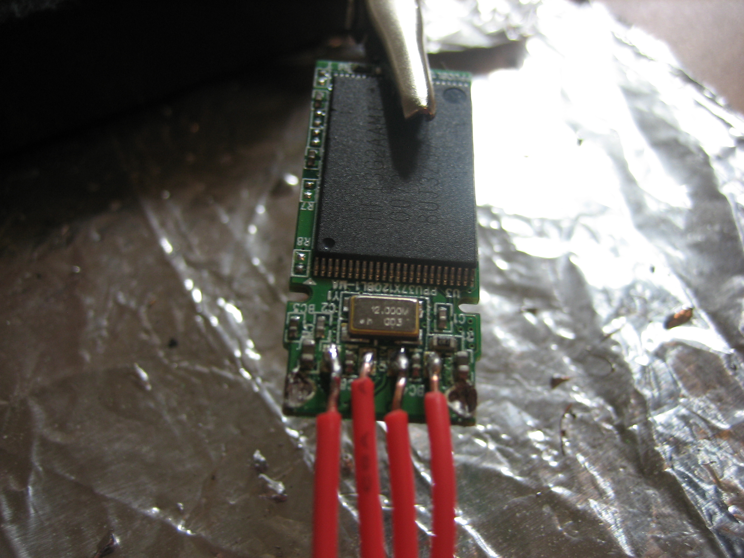
Lastly, to see if I destroyed anything with my shaky hands or overheating of the component it was due for a quick test. I took some 22 AWM solid wire, clipped four equal lengthed parts, stripped the tips on each end, and soldered each lead to the USB pads. Then I held the wires close together, made sure I had the orientation correct for the drive's top&bottom, and pressed them to a USB port on a PC and it was recognised as a removable memory drive. Note, I do not know whether the above could cause any damage to the PC, so research it and tread lightly. You are responsible for your own actions, even in America (Where it seems less and less these days)!
The result photos are below, they are clickable to see higher resolution for more detail.
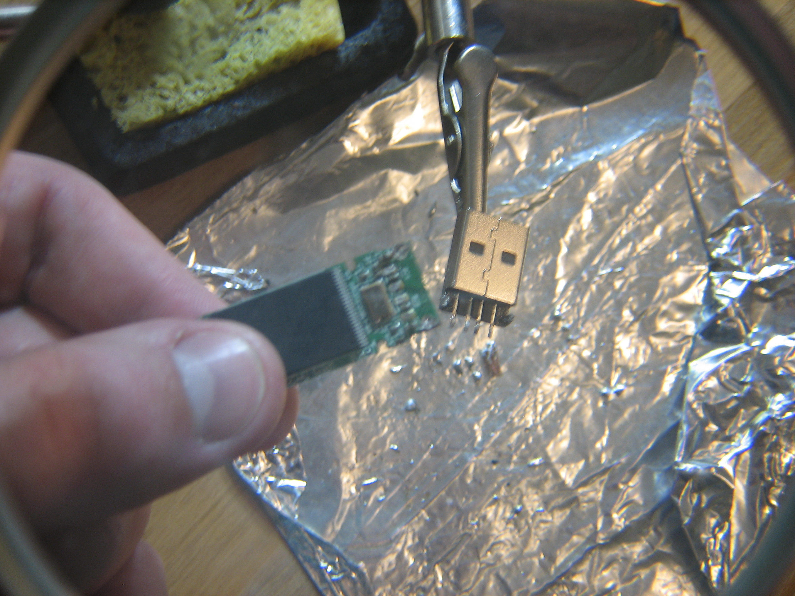
Disconnected!
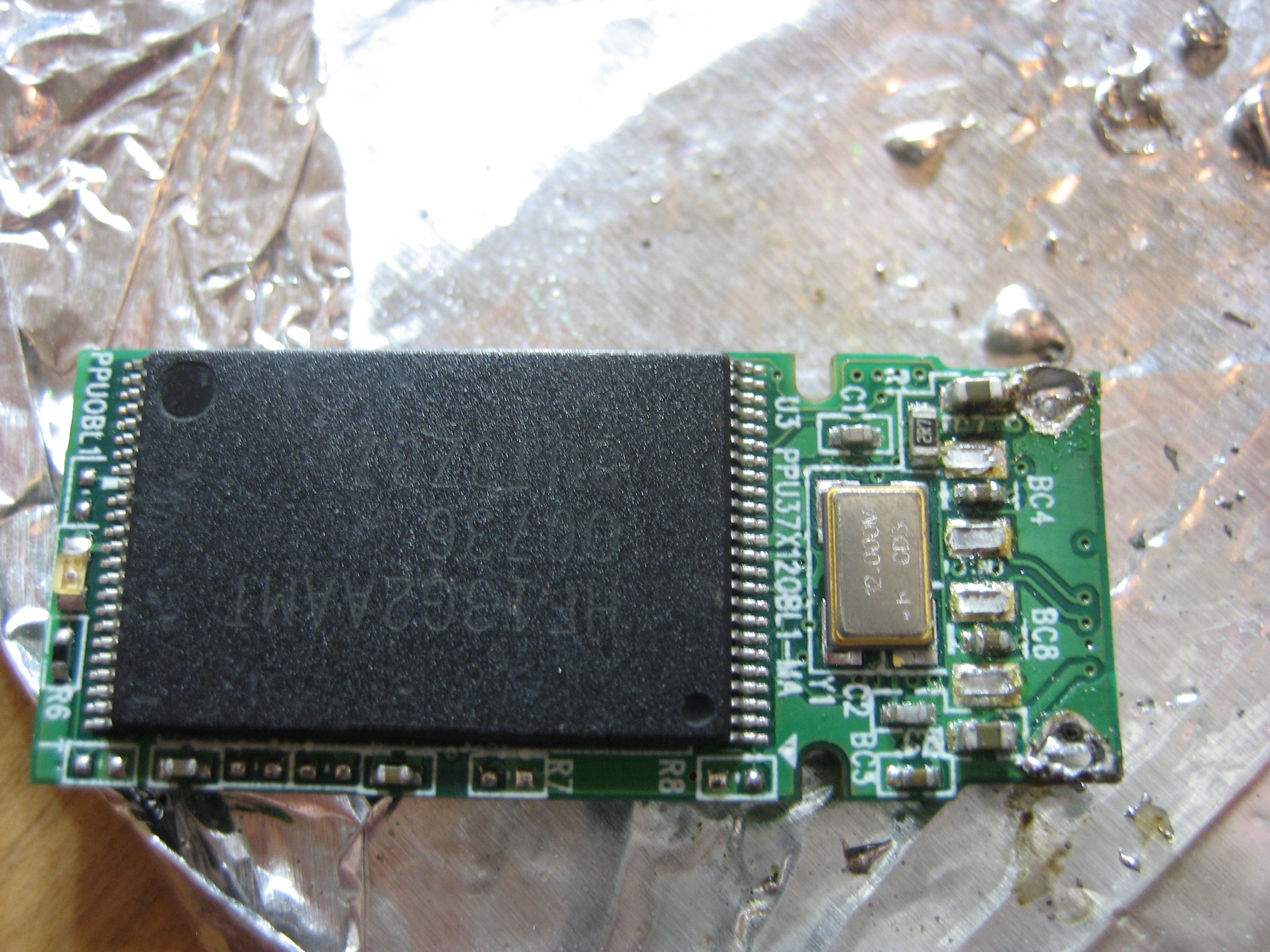
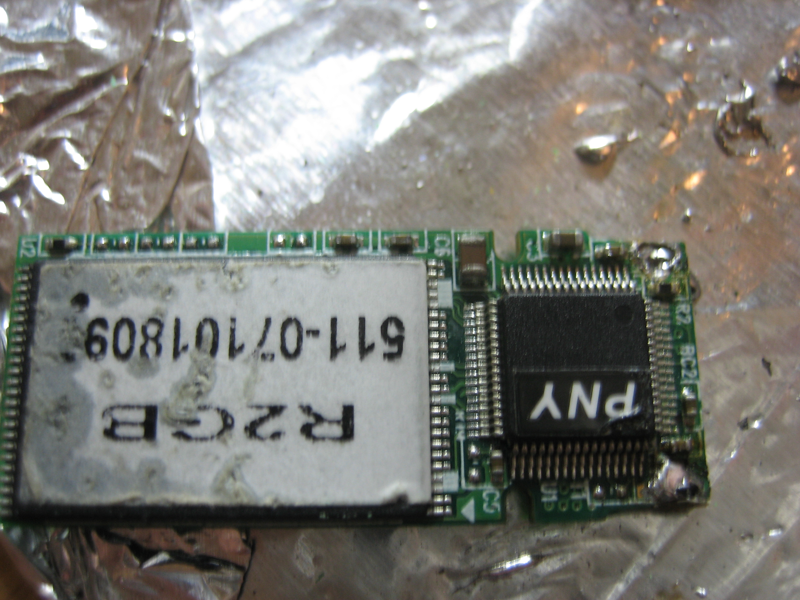
Flash Module Top then Bottom.
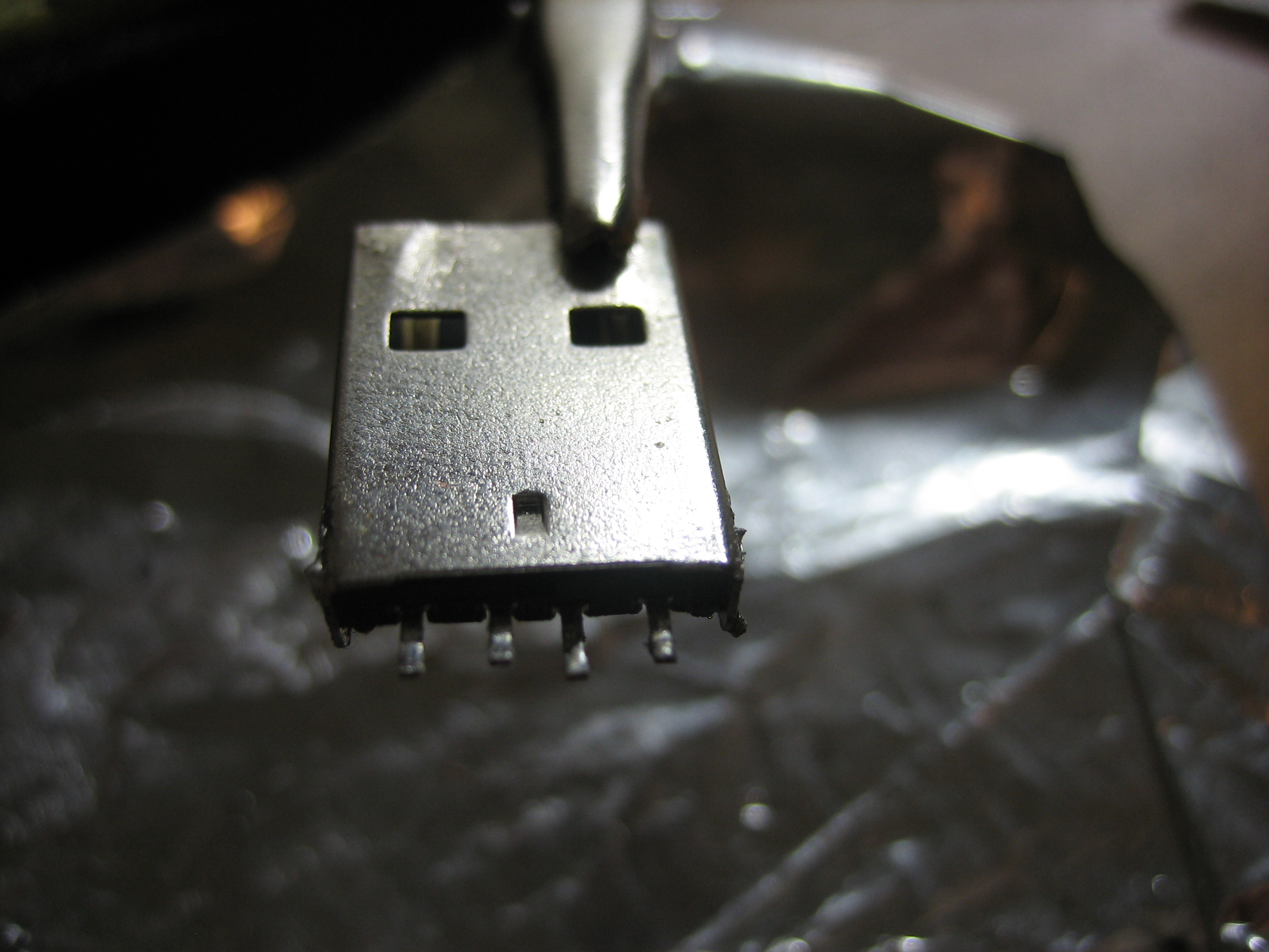
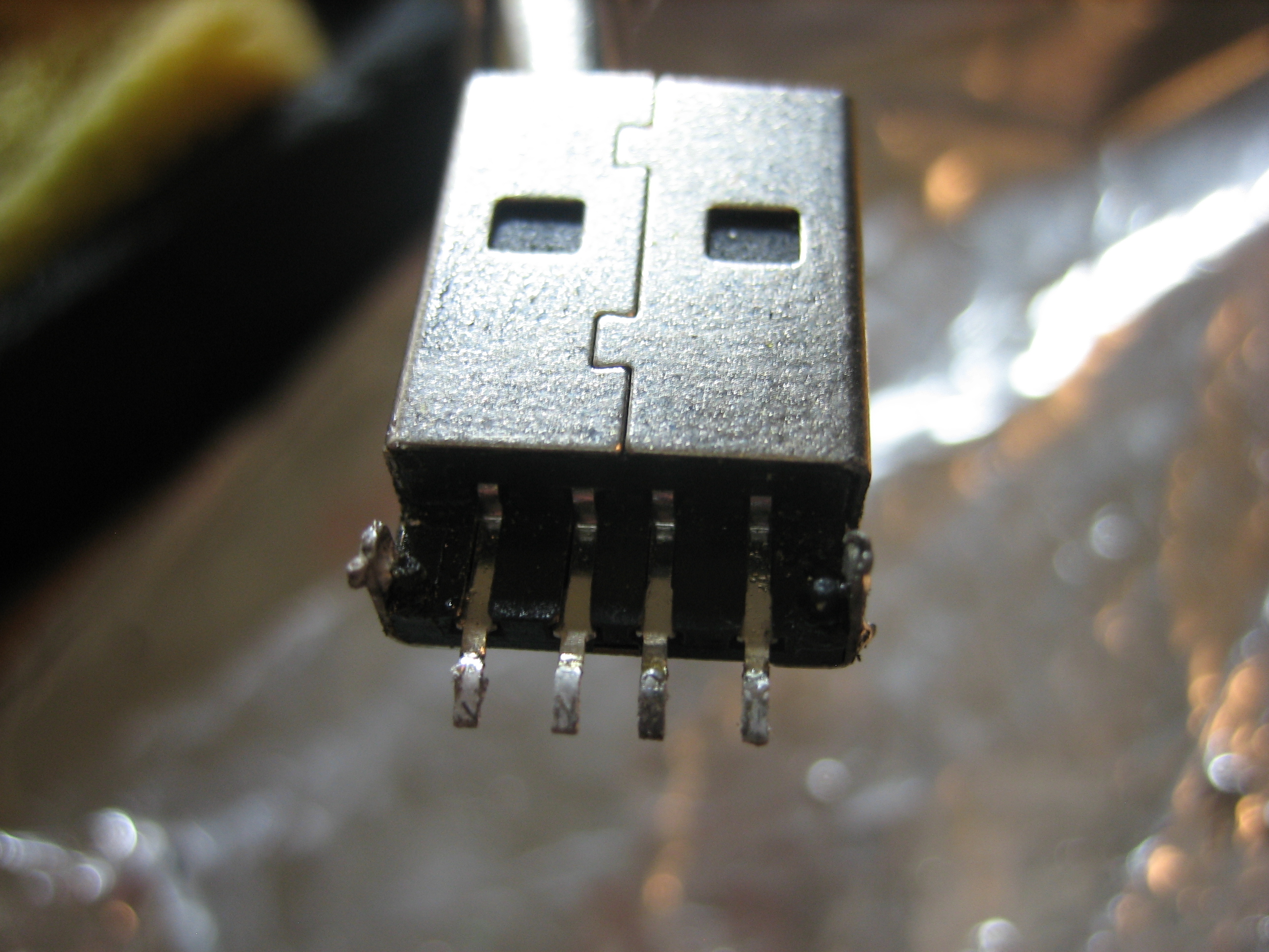
USB Connector Top then Bottom.
Finished!
Comments
If you mentioned how long it took you to accomplish this, no one would be impressed. You were probably not good at this either:
http://en.wikipedia.org/wiki/Operation_(game)