February 18, 2008
Modifying an EEE PC Preparation Pt. II
I cancelled the EEE PC that was on order since buy dot com had some lethargic purchasing rules. Instead, with the long weekend I visited a store called MicroCenter which stocks the device. They had the 4G SURF in white in stock, but not the one with the webcam. That should be fine for my intents and purposes. Now that I am an EEE PC owner, it was time to stock up on the missing parts. The OS was pretty interesting, many strides have been made in Linux with Xandros and probably other distributions, however the dual boot situation will cause more hurdles than it is worth to me and I will opt for Windows XP for my device.
The next part of the weekend involved getting a Patriot 32GB USB thumb drive which will be embedded inside the EEE PC. This was costly and bought at the local Frys, at 250$ and a 50$ mail in rebate to eventually knock it down to 200$. The Crucial PC 5300 SODIMM II 2GB memory module was not too bad at 60$ minus an eventual 30$ rebate at Frys. I installed the RAM upgrade and verified functionality. What a hoop to jump through for access to the slot, it involved taking apart the whole bottom portion of the EEE PC. Following this instruction proved the task quite easy (Guide).
The last item to speak of in the Frys expedition was a rotational hub that seems small and popular to embed within the EEE PC. The cost was 15$, but you can do better online. The rest of this article will be explaining the disassembling of it and the mapping of USB signals. Click the next link to see more.
With one of these hubs with 4 USB slots I should be all set. I do need some equipment so I have ordered Kapton Tape, Kynar wrapping wire @ 30 AWG, and a 12 watt Weller Soldering Iron with a really fine tip. The items I want to populate on it are: FM Radio (SiLabs USB FM Radio Dongle), 32GB USB Flash Drive (Patriot Brand: for the installed programs and swap file), a USB Bluetooth Dongle (With it I will be able to interface with my USB GPS from Pharos), and probably a smaller USB flash storage to move the swap file for the churning of its lifecycle. That's all ahead though, so on to the rotational USB Hub disassembly.
This is what the item looks like when I took it apart.
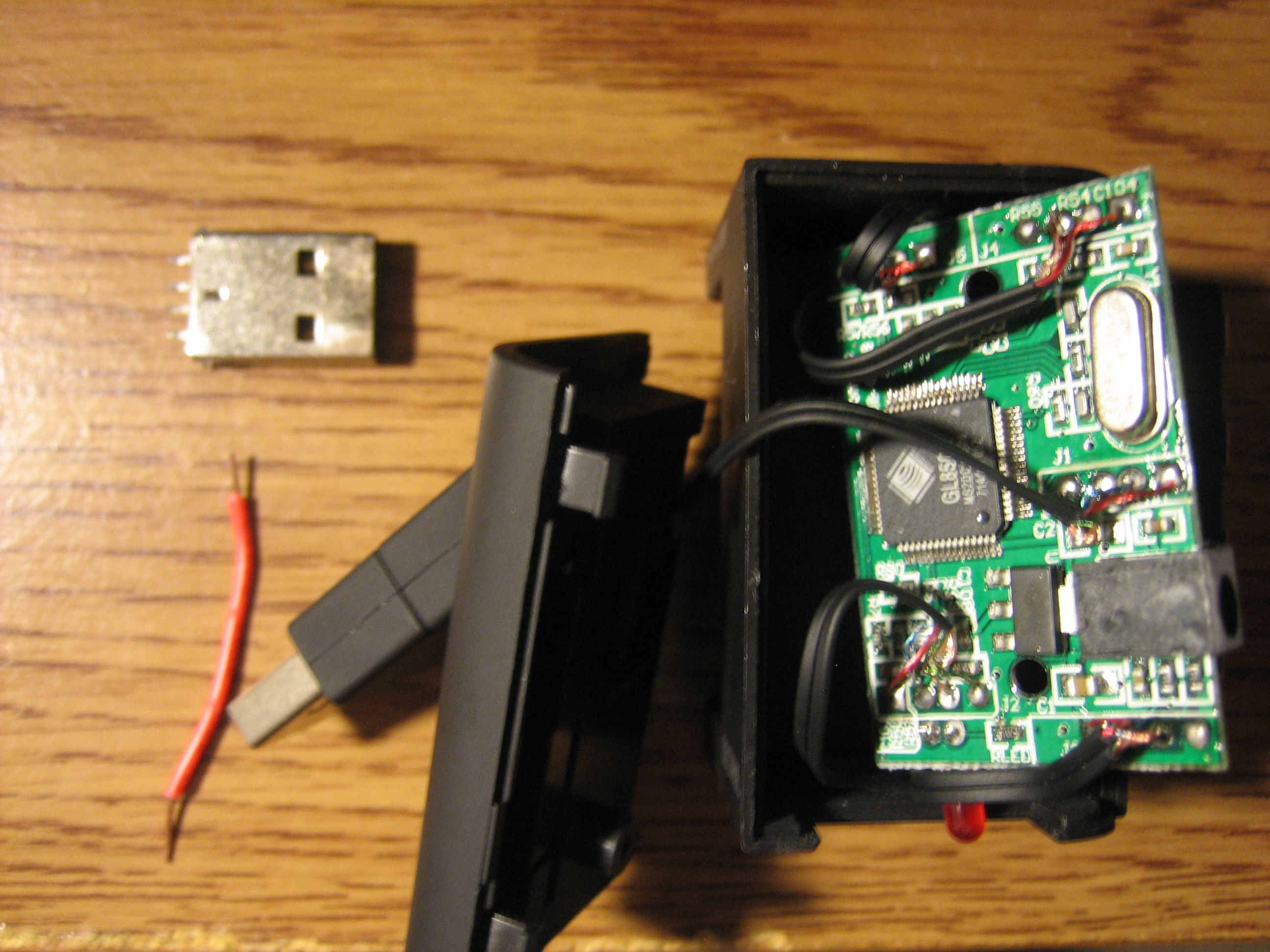
The pieces here from the lower left and clockwise: A piece of wire, so I could do a continuity test on the USB part that plugs into the PC since my multimeter leads can't fit into the gap between the grounded shield and the 4 USB pins, the USB plug that you saw the last go-around (here) which was used for the continuity testing of each of the 4 hub ports for devices to see how they map on the circuit board, and lastly the hub taken in parts where I used a No. 1 phillips head screwdriver to remove the screw near the plug that goes into the PC and a 1.4mm flat head screwdriver to pry apart the casing without breaking any leads or wires.
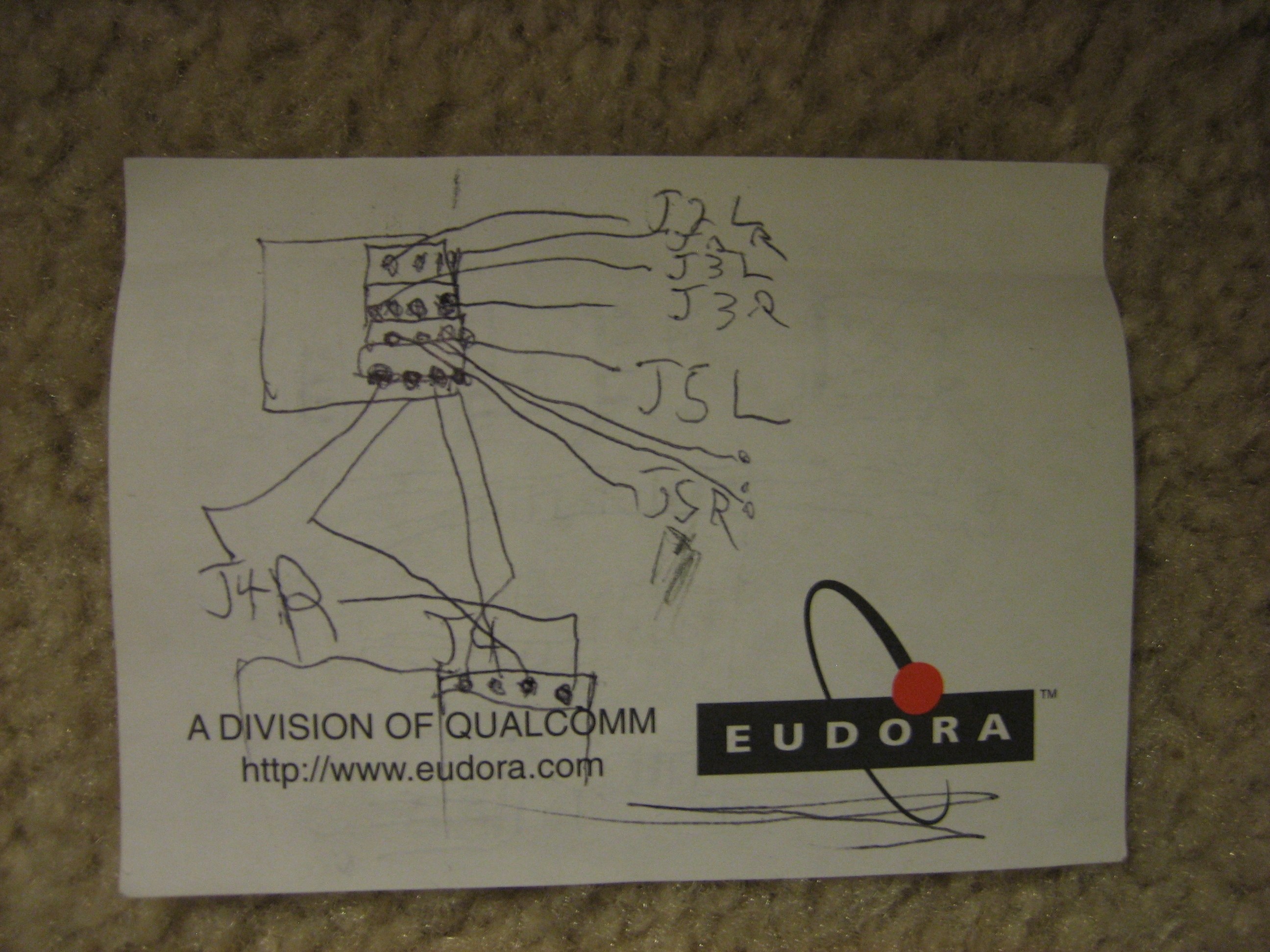
Using my multimeter, pen, and paper; I drew a rough sketch of the connectivity points between USB pinouts and the way they are arranged on the circuit board. These are shown here:
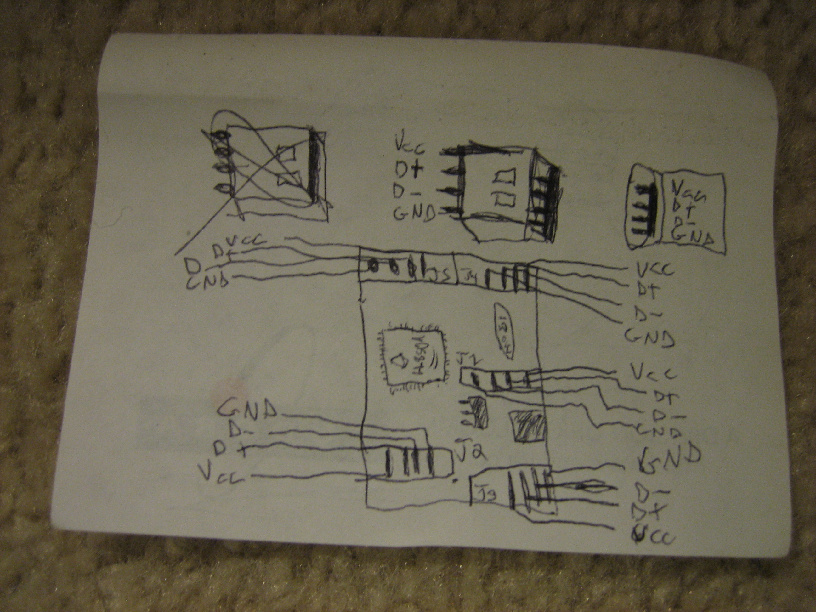
Since that's not a good diagram to work with when actually using it in the EEE PC, I cleaned it up a bit and added a provision for the part that will plug into the onboard USB connector. This diagram is shown here:
The next step is to remove the wiring from the USB Hub PCB, the LED on it, and the power plug with the 12W Weller Soldering Iron when it arrives and to check that it is still functional after the operation. Then there will be some connecting of devices, verifications, and Windows XP OS install on the EEE PC.